NMEA – National Marine Electronics Association
“NMEA 0183 is a combined electrical and data specification for communication between marine electronic devices” (Wikipedia)
The issue:
Wireless sports a complete B&G H1000 electronics/navigation suite, including wind, speed, depth, auto-pilot and chartplotter (CND). This system was one of the best available 15 years ago, but has since been replaced and out-done.
Now while my system is working without any issues, I have decided to make some improvement to my onboard electronics, and it has been an uphill battle sorting through the world of marine electronics on my own.
This post (as it continues to develop), should serve to assist anyone with an outdated chartplotter/autopilot controller who wants to utilise good existing instruments with a state of the art software and hardware package.
It is the story of 2 generations of upgrade. Initially I simply wanted a GPS signal routed to my Icom VHF radio. Then as my knowledge of what was possible grew, I decided to replace the CND unit and develop a DIY navigation system.
PROJECT #1 - GPS TO VHF
1. Get a signal from my GPS antenna to the NMEA input at the back of my ICOM M602 VHF, in order to display a back-up GPS position, but also to enable my DSC (digital selective calling) and location-enabled distress signal. The ICOM M60f2 allows you to broadcast a per-determined nature of distress and a GPS location to any vessels in the area with a DSC unit (the Coast Guard in NZ do not monitor DSC on VHF).
The B&G H1000 system is comprised of a masthead unit which produces data on wind speed and direction (recently refurbished), a depth sounder, a knot meter, a compass sensor unit, and a GPS antenna. These units collect data which is fed to the CND unit, which is also the chartplotter and ‘brain’ of the system. The information is processed, and distributed to the analog wind display, the multi-function LCD display, the autopilot display, and the autopilot itself. A tremendous amount of data is available to me while underway, from SOG to the location of the nearest fuel depot.
The B&G units all talk to each other over a B&G-only system called Fastnet2, but the language used is NMEA 0183. My system incorporates a special unit called a “Universal Interface”, which is like the “back-door” to the system. This interface allows non B&G components to send and receive data (0183) to and from the H1000 system.
The Universal Interface
I can achieve my goal by using connection 1 (NMEA tx+) behind the black cover. This is the NMEA 0183 transmit connection from the overall system. You can see the inside of the box here:
B&G Universal Interface
The wires you see in this photo are connected to the alarm, letting me know when I’m about to aground, when I’ve dragged anchor etc.
This option would limit my ability to eventually extract data from the system into a multiplexer, so to simply extract a GPS signal, there was a better way...and that is the CND 'black box' inside the electrical cabinet.
The CND (Chartplotter) PWR Box
CND PWR box internals
Solution
The best place to grab an GPS nmea 0183 signal is from the CND PWR box, which is where the chartplotter and GPS antenna come together to be energised, but also where they connect to each other.
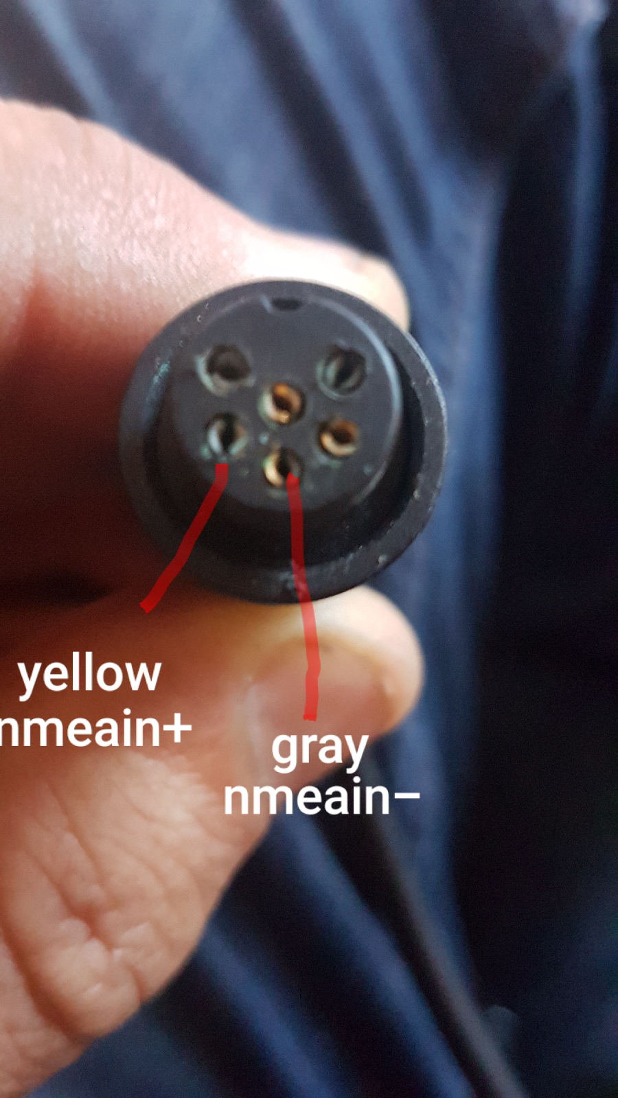
Connect the GPS to the VHF at the CND PWR box.
The method for connecting the GPS to the VHF from the CND PWR box is to connect the blue wire from the CND/Chartplotter (NMEA OUT +) to the NMEAIN (+) pin on the back of the VHF. Then you connect the black wire from the CND (NMEA OUT -) to the NMEAIN (-) pin on the VHF. You can see both wires in the photo above.
 |
| NOTE!!!!! This view is of the radio input, the cable is mirrored |
I have to take a minute to recognise a real guru on this subject, who really pointed me in the right direction. Here is the secret:
John,
You can get GPS information from 2 places in your system.
- From the Blue (Data +) and Black (Data -) on the data / pwr cable that comes from the H1000 CND. (See page 46 of the attached manual). This is in the Junction box that you have identified and you can see the blue wire in the photo.
- From the H1000 Universal Interface terminal 1 (Data +) and Terminal 2 (Data -)
You should be able to use 1 of these outputs to feed the VHF radio and the other one to feed the MUX. I would use the UAI output to feed the multiplexer as the CND NMEA output does not supply wind information.
I hope this helps.
Best Regards
Craig McMillan
Advance Trident
UPDATE 31/7/13 - I have completed goal #1, specifically the connection of the GPS antenna to the VHF radio and the input of my MMSI ID. I can now use DSC to alert other boaters should I have an emergency.
 |
| Note the positon information now displayed on the VHF. |
Thank you to the guys at
Bay Marine Electronics in Tauranga, NZ. They had the tools to find the data stream from the GPS and get it into the VHF.
Also worthy of note is the wiring color codes of the GPS antenna itself.

After painstaking research over a couple years...
Project 2 ~ New DIY Navigation System
This is my chosen path to replace the B&G CND unit, and fully-integrating my nmea 0183 data (from instruments) with a modern navigation package, AIS, and data from my charging system, engine, and onboard tanks.
NOTE: The B&G instruments receive power from the 4 way HUB and therefore do not rely on the CND unit for the small amount of volts they consume. This comes from my DC breaker panel. This allows me to delete the CND without compromising the instruments.
There are several components to research and source, so I will be detailing each step along the way. Suffice to say I will be running
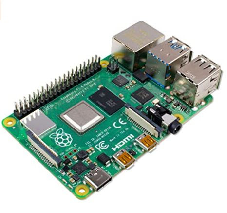
Openplotter (opensource/FREE chartplotter software) on a Raspberry Pi 4, monitored on dual screens, one in the cabin and one at the helm.
This solution will cost approximately $400USD in total, approximately 1/10 of the cost of a new B&G navigation system!!
Here's the heart of the system, a Raspberry Pi 4 Model B 2019 Quad Core 64 Bit WiFi Bluetooth (4GB):
And this is the cooling case for it:
The Raspberry Pi will display on a Eyoyo 2K Portable Monitor (mounted on the bulkhead in place of the current chartplotter).
To get data from the B&G instruments, GPS, and AIS to the RPi (computer), and then to send data back to the autopilot, I will need a multiplexer (MUX). This device combines data coming in from different locations and at different speeds (baud rates) into one output (USB) that can be sent to the computer.
I selected a simple and affordable ($89 USD) unit manufactured in Australia by
YakBitz
All of these parts are in transit....watch this space!!
17/9/21 Update!
Here is the Raspberry Pi4b hot from the courier, I am installing it in a cooled aluminum case.
These things are TINY! I imagine all of this will be easy to install discreetly.
Update 22/9/21
Here's the recommended wiring between a B&G H1000 Universal Interface and the Yakmux unit, courtesy of Steve at
YakBitz.
23/9/21 - Refined drawing showing power and data connections to existing equipment.
Update 25/9/21
The removal of the CND unit will leave a hole, needed a plate to cover and act as a base for the new monitor or equipment (placement tbc). Still had some scrap teak. Bit of cutting and shaping and oiling later...
Update 4/10/21
I've created a mounting board from marine plywood, and stuck it to the inside of the bulkhead (in the small locker starboard of the companionway) using 3M 5200. This will allow me to screw down the required components. To hold the panel in place for curing I used what I had at hand...a teaspoon.
Here is the Yakmux unit wired at one end.
I'm not sure yet how to open the jaws on the B&G UI end of things.
Update 6/10/21
I think the most challenging part of the project thus far has been running the wiring from the starboard instrument locker to the port side DC panel and navigation station. A convoluted series of small openings and transition over the engine meant moving back and forth between the cabin and engine room. I accomplished 3 objectives:
- Pull the GPS antenna cable back to the instrument locker from the black junction box (see older post above) in the DC panel cabinet. The GPS cable will be wired directly to the Yaxmux.
- Pull a 7.5a cable from the instrument locker to the DC panel
- Pull a long USB cable from the Yakmux to the RPi at the nav table.
I then installed a terminal post in the instrument locker and confirmed 12v. I wired the Yakmux to the B&G Universal Interface and the GPS antenna to the Yakmux. Power and ground was applied to the Yakmux and antenna (the UI is powered along with the entire B&G system from the DC cabinet 4-way box).
The very small wires connecting the electronics were soldered or crimped as required, I'm not a huge fan of dealing with tiny wires tbh. The Yakmux and GPS antenna draw milliamps.
Turned the system on and proceeded to look for a signal in Openplotter and Signal K (more on this later) and can confirm that data is being received!
 |
| Grainy photo...tiny wires |
 |
| It's ALIVE!!! |
7/10/21 SETBACK!!
My B&G 4 Way Hub has shorted out. The 5amp circuit breaker tripped and I traced the problem to a corroded and broken pin on the B&G 4 way hub power connection.
The 4 way hub connects the instruments at the forward end of the boat with the instruments and equipment at the aft end of the boat. It also introduces 12v DC power and grounding to the system through a cable that looks identical to the Fastnet2 cables, but has only 2 wires (Red + and Blue -).
It was at the power connection that the pin burned out and damaged both the hub and the power cable.
This takes down all of the instruments until I can find a replacement. The system is discontinued so this might be a challenge.
 |
| 4 Way Hub |
 |
| Fastnet2 connector |
Update 8/10/21
I have located a new/old stock B&G H1000 4 Way Hub in Florida USA. It is being couriered to NZ and should arrive in a week or 2.
As I have had no luck in finding the power cable (which is known as H1000HCP in the B&G literature), I am forced to create one.
Because the B&G chartplotter is now redundant, I have 2 useable Fastnet2 connectors at either end of the chartplotter's cable. This cable, unlike the HCP power cable, has 4 wires with a shield rather than 2 wires.
I need to understand how the original power cable was wired if I am to replicate it with the spare cable. I used my multimeter (ohms) to test continuity and found the following arrangement:
On the H1000HCP factory cable (PLEASE REFER TO THE DIAGRAM ON THE RIGHT, WHICH IS THE CABLE), the red wire (+) went to hole #1, and the blue wire (-) went to hole #5.
On the cable I have available to replace it, I have discovered that the red wire also goes to hole #1, and the metal shield goes to hole #5. So this confirms that I need to apply 12v to the red wire, and connect the shield to my negative bus bar.
 |
| Image on left is the hub with male pins. Image on the right is mirrored, and represent the female cable end. The confirmation of the color of the 3 data cables come from Oppedijk.com |
If you are struggling to understand the B&G Fastnet2 system, please spend some time on the following website:
Update 15/10/21:
This arrived today all the way from Florida USA! Might be the last one on the planet but it will put me back into action next week.
 |
| Black instead of yellow, but this is the real deal. |
Update 21/10/21
I have finally got the system figured out, with all of my B&G H1000 instruments and the GPS antenna sending good data to the RPi4 and Openplotter.
This was not straightforward at all, and at first it didn't work. I got some great help from Steve at
Yakbitz. He looked at the data that was coming in from the B&G network and immediately suspected a voltage drop imbalance. Briefly, this is when the voltage drop on the Tx+ or Rx+ lines differ substantially from the drop on the Tx- or Rx- lines. Voltage drop occurs in any wire over distance, so the distances must be the same.
Because I was connecting the Tx+ and Rx+ leads from the Yakmux to the B&G Universal Interface over a distance of about 100mm, and the Tx- and Rx- lines were being grounded all the way back to the DC panel (3meters), the differential voltage drop was enough to corrupt the data stream. I grounded the negative data lines to the screen inside the UI and this instantly fixed the problem.
 |
| Data + lines (green and yellow) are the same length at the Data - lines (black) |
I am tempted to start some sort of B&G H1000 help forum. I really think this gear is top quality, but it is older and has been abandoned by B&G. I have learned so much about how it works now I'm sure there are others faced with the prospect of replacing good gear when they want to upgrade a single component.
Next I will be refining and developing the system to include dashboards, a 2nd monitor at the helm, integrating the system into my autopilot, and creating a panel to display my battery data, tank, and engine data. I will also re-connect my VHF to receive GPS data using an RS485 connector.
 |
| USB to NMEA cable |
 |
| ICOM 602 wiring |


