Tuesday, 2 July 2013

On the hunt for an electrical gremlin!

Some weeks ago I went down to the marina to run up the engine, as I do religiously every week.  By now the days in New Zealand have gotten fairly chilly, but I was still surprised when my near new Westerbeke 35D3 (400hrs) took 7-8 long seconds to fire, despite holding the glow plug button for well over 15 seconds.

This problem has continued since, and I initially considered that the colder weather was demanding longer glow plug times, but 10 seconds or 30 seconds, it made no difference.

I checked the glow plugs for increased resistance, but they all checked out OK.  So if there is good heat in the plugs, and plenty of air, then it must be fuel.

  • It must be noted that once the engine starts, it runs like a top.
  • It should also be noted that the initial attempt at starting takes a considerable amount of cranking, but if you then stop, turn the key off and try again, the engine starts instantly.

One night last week I was pouring through the electrical schematics for the engine and control panel when I came to understand how the overall pre-heat and starting systems work.

The 35D3 has a low-pressure electrical lift pump that pressurizes the fuel system before the engine starts, then keeps pumping fuel toward the main injector pump as long as the oil pressure stays constant.

What caused the light to go off in my head is that the glow plug button on the Admiral Panel sends power to the "Pre-heat solenoid", and this solenoid does 2 things...it activates the glow plugs, but it also activates the electric lift pump.

  • When I depress the glow plug button, I do NOT hear the steady clicking that I should from the electric fuel pump (!)

IF the solenoid wasn't working, or IF there was a bad connection to the lift pump, then there would be no fuel pressure waiting upstream of the injector pump for starting.  Several seconds of cranking would cause the injector pump to pull fuel toward itself, and then it would fire easily on the 2nd attempt, which is what I have found in practice.

I will use the electrical schematic (http://www.westerbeke.com/Products/ProductWiringDiagram.aspx?ID=1275) to look for 12v from the lift pump all the way back to the glow plug button on the panel.  If I have 12v all through, then I'll follow Westerbeke's advice and whack the pump with a mallet (seriously...this is in their manual).

I'll update this post as I work through this problem.


4/7/13 - UPDATE

I spent some time last night onboard with my multimeter chasing the fault at the lift pump, which I can confirm is not working when the start-up procedure is followed.

I confirmed that the pre-heat solenoid is indeed functioning, there is a loud click when the glow plug button on the panel is depressed.

The lift pump has only two wires, a 12v hot lead and a ground (earth).  The 12v lead is connected to the pre-heat solenoid with a spade connector.


 I pulled this apart and put the positive probe of my multimeter on the lead coming from the solenoid.  I grounded the negative probe against the engine block (a clean spot of metal).  I set the multimeter in the companionway in such a way that I could observe it as I turned the ignition key and depressed the glow plug button.

Instead of getting 12v, I got a reading that varied between 3v and 4v.  This is my first indication that the lift pump may well be capable of working, but is not getting sufficient voltage.  I can confirm this tonight by bring my small 12v spare motorcycle battery down to the boat and energizing the lift pump directly.

Normally in the past when I see anything less than 12v, I immediately suspect corroded wiring or connections, as voltage drop is the first sign of increased resistance.  I am also wondering if the 10amp breaker that resides on the solenoid terminal  (see part group #20 on the parts diagram below) is faulty.  Testing for 12v just before this point will confirm. 

I do suspect that this will prove to be a 2-person job.


UPDATE

I stumbled across this account of a very similar situation at another owners website (http://aboardastraea.com/).  It is VERY interesting in that this owner also expereienced 3.96v at the downstream side of the solenoid (I mention above that I was reading between 3 and 4v).

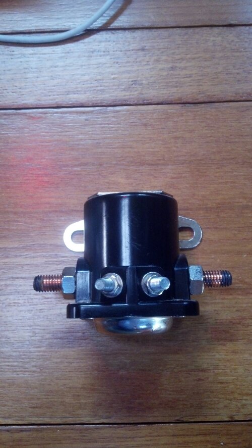
It seems that for the realtively-low cost of a new solenoid, I should give it a try.


wpid-2012-12-09_10-38-06_115.jpg

Preheat Solenoid Replacement

|
Las weekend when we were anchored in Glorietta Bay the engine was hard to start. When you start our engine first you turn the key on, then an alarm sounds. Next push the preheat button and the alarm turns off, the glow plugs heat up and the fuel pump comes on. In Glorietta the alarm never turned off and the fuel pump didn’t come on. Solenoids are easy to troubleshoot. There’s a 12VDC input at two places, one is the high current input on the left copper post, and the activation is the bottom left small post labeled “S.” When 12VDC is applied to the “S” post it activates the internal mechanism completing the circuit, essentially electrically closing the switch and allowing electricity to flow from the left side to the right.
image
During troubleshooting I verified that the 12VDc was available on the input. On the output side the large post was 0VDC and the small post was 3.96VDC. I individually disconnected each load on the right side to verify. That they weren’t loading the solenoid down and found the 12VDC never goes all the way through. I looked the part number up in the Westerbeke manual (part number 024639) and found it online for $42 plus shipping and handling. Fortunately, the solenoid is the same as for a 1967 Ford Mustang so I bought it at O’Reilly’s Auto Parts for $24! Thanks to my buddy Vince for knowing that solenoid off the top of his head. I installed the new solenoid last night and it works perfectly now!

Thursday, 27 June 2013

Sacrilege?

Sailing on a beautiful summer's day, with the warm wind blowing through the cockpit...there is nothing on earth as wonderful.

Sailing on a wintery day, with ice-cold rain and sea spray running through your hair, down your back and into the waistband of your shorts...not so good.

I am also faced with the reality that my young family need to be protected from the extreme NZ sun, as we sit pretty much directly under "that hole in the ozone" that we have all known about for years.

As a result, I have been investigating the installation of a bimini to compliment my dodger.

But...will a bimini protect me from a cold wind off the beam?  Will a bimini allow me to mount my instruments overhead and allow me to mount solar panels on top?  I believe from my research that the answer is no.

So then some sort of hardtop is required.  There are certainly a few examples of hard-top bimini installations out there, most of them being the products of Genco Marine.

I very much like what was done here:


Unfortunately, the cost of importing something as unweildy as this from Canada to New Zealand makes it a bit of a non-starter.

I began to wonder if I couldn't come up with a home-grown solution.  I have been playing with some photographs to come up with a possible concept.

I have always admired the lines of the Fisher motorsailers, with their enclosed wheelhouses:


I try to imagine that wheelhouse extending back to the stern, as would be required on a Nonsuch. 

I have also found inspiration in the design of the Chesapeake Marine Design Oysta 28:


There is a Nonsuch owner out there who has built this timber dodger on his boat:


Thank you to the owner in advance...


...and I've been playing with those lines, brought back to the stern:


A bodge-job with Microsoft Paint, and way too long...but you get the idea. The entire thing could be white, instead of varnished timber, for a very contemporary-look


Now imagine this overall profile, but with the forward sloping forward section or "Portugese Bridge".  There are clearly issues of access and sight lines, which could be resolved before final dimensions are set, but in concept, imagine having a warm dry cockpit with windows that could be opened in the summer, a couple of hatches on the roof, solar panels, and fitting on the ceiling for a remote VHF, plotter and instruments?

I'm actually convinced that the cockpit could then be far more useable year round, be it in the blinding sun or the cold and wet.  It would add tremendous safety for the kids as well.

Of course you either love it or absolutely hate it, and it would be criminal to ruin the lines of the Nonsuch, but perhaps if the wheelhouse roof curvature matched that of the cabin exactly, it might actually really work?

Wednesday, 26 June 2013

Cabin sole re-finishing

From the start, I began to suspect that the very clever and beautiful cabin dining table would prove more of an obstacle than anything else, and I was right.  
The table is large enough to serve everyone seated on the starboard side, and when unfolded it does the same for the port side diners...the problem is when you add up the number of times you eat with a large group of people, and compare that to the number of times you wrench your back trying to access the lockers behind this bloody table, or wish that you had still more floor space for the kids to play...you realize the table must go.

So...a couple of weeks ago I did just this, I pulled the table off the boat.  No real drama, it's not as heavy as it looks.

But like all small projects, it grew in size and complexity.  I noticed that the teak & holly cabin sole was discolored where the table legs sat for 26 years, and that the cabin sole in general was rather dull.


I knew that I wanted to make some changes to the plumbing and clean up the under-floor wiring, so I removed all of the sole panels.


I took the panels home and washed them.  I then sanded them lightly and carefully with 180 and then 240 grit with a random orbital sander.

I applied 3 coats of Cabots CFP Water-Based Flooring Polyurethane (formulated for skid-resistance when dry),
and was extremely-happy with the end result.


The space down below now is remarkable, the measurement between the base of the port and starboard settees is actually just over 1.5m, which can be better appreciated if you pull it on a tape measure...this on a 30' boat!


Monday, 3 June 2013

Tank Monitor Installation

Hello again,

Kiss Kiss has three water tanks (port and starboard cabin, and bow), a small holding tank above the head, and a factory fuel tank (modified and renovated in an earlier post).

I wanted to know the fuel level, and the water level in the two cabin water tanks.  The bow tank, due to my insecurities over having that much mass at the bow, has been taken offline.

The port water tank is factory original, with an electronic level sender installed.  The starboard tank is a poly replacement for the original holding tank, and does not have a sender.  Because the two tanks are linked when both valves are opened midships, they will self-level...therefore only one sender is required (and some math during calibration).

The fuel tank also has an electronic sender.

I have a BEP multi-tank monitor which will keep track of 3 tanks simultaneously once properly calibrated.


Installation required running 12v to the extremely low-draw senders, fusing and grounding them, then running the sender leads to the control unit, which I switched and fused and installed adjacent my chartplotter at the navigation table.  I have not calibrated the units yet, because the instructions insist that you calculate the fuel/water volume, divide into 5 parts, then empty the tank, fill in 5 equal amounts while calibrating (a bit of a pain).
I am thinking whether the same couldn't be acheived by pulling the sender out of the tank, measuring the long sensor rod and dividing it into 5 parts with a marker, then dipping it down into the full tank mark-mark...not sure this makes sense with a non-rectangular/non-flat tank...geometry....