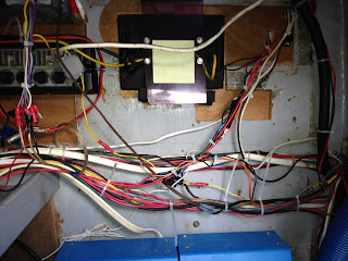
I had been noticing that the electric head was getting intermittent, and was slightly dimming the lights when used.
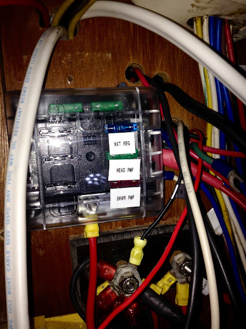
I investigated, and found 14awg wire, with a half dozen old butt connections. This line terminated on a glass fuse block from the 1980's.
The head pump draws 20amp, and the run is 7meters !!! Clearly this was dodgy.
I ripped out the wire from pump to panel, ran 10awg (5mm2) and installed a new blade fuse block.
I made sure to use marine connectors, and my high-end wire strippers and crimper (good tools are really important with wiring).
Once sorted, the pump roared to life, and spun 50% faster than it had been.
Huge resistance in the old cable run, had it been a constant draw device, there may have been a fire.
How did this happen? The head was installed by the previous owner, and he had no idea on wire gauge - amperage - length.
I have a free app that calculates wire size, fuses and breakers. There really is no reason to bodge together a wiring job. If in doubt, check online. How many amps the device draws, how long is the run, is it in the engine room, how many wires will be bundled together. It's all straightforward.
Get some ratchet crimpers and side pull strippers. Use marine heat shrink connectors and tinned wire.
In any case, all sorted.
I'm going to redo all the wiring in this way, one circuit at a time.
Beware owner-modifications!!!
John
UPDATE 13/12/14
I have finally made some real progress with the improvement/modification of the onboard DC electrical system.
At the moment the positive leads to all of the electrical loads on the boat go directly from the hot side of the circuit breakers. This is not good practice. Rather there should be a distribution block that allows a short and organised lead from the breaker to the block, then from the block to the load.
I also needed to create organised and efficient bus bars for the ground wires from all of these loads.
Finally, I needed to add all of this in a way that completely-militarised my electrical cabinet, with every wire run cleanly and securely.
Step one was to give myself a firm platform for mounting all of these blocks, bars, as well as the existing hubs and regulator.
Here's what I built, a simple plywood panel, with a horizontal shelf that maximises the surface area in an otherwise cramped area.
Painted and installed:
And the wiring/mounting underway:
The shelf will host the distribution block (min 14 points required) and the area just below the alternator regulator is an ideal spot for the new 18 way Z-bar bus bar:
(Photo is of the 10 way unit)
It's all underway now!
UPDATE 16/12/14
The work is now well underway, with the installation of the terminal blocks, the ground bus bar, and the acquisition of 14 new Blue Sea circuit breakers.
I've removed the brittle old LED indicators, which were a mixed bag of spade terminals (do NOT use spade terminals on a boat) and tape.
This helps clean up the panel by removing 28 leads and terminals. I can now methodically upgrade each circuit one at a time.
Spaghetti!!
LEDs gone, some room to move
Typical corrosion and inferior terminal.
You can see the 16 x 30amp terminal points, 2 B&G hubs, the regulator and in the top left the Marinco Z-bar grounding bus. Only the new LEDs will be grounded directly to the panel bus(es).
UPDATE 19/12/14
I have essentially completed the renovation/re wire of the circuit panel. It took approximately 20 hours.
BEFORE:
AFTER:
Now to tidy up the wiring as it leads from the cabinet through the bulkheads under the cockpit. But perhaps another day...
High quality LED indicators purchased from www.bizfarm.co.nz
Be sure to ask for the 12v units, as they also supply 24v
UPDATE: 21/10/16
I'm now planning to continue the electrical upgrades to the boat, by organising and re-working much of her electrical wiring. I have mentioned previously that the engine room/back of cabin bulkhead is a nest of wiring bundles, un-labelled and running everywhere.
In order to begin to sort this mess out, I need to identify and label each wire. The challenge of tracing each wire back to its source will be made possible with the purchase of a wire tracker/tracer, which energises each wire at its source and then allows me to find it remotely.
 |
| Sperry Instruments ET64220 |


 Update:12/12/16
The new engine mounts are in, and they look very robust.


